Technical and Economic Assessments of Cogeneration Systems
Cogeneration systems provide both electrical power and a thermal commodity. The thermal commodity may be hot gases, steam, hot water, or chilled water (produced via an absorption chiller). The thermal commodity is produced from energy sources such as the exhaust of a gas turbine that would not be used in a non-cogeneration application. Overall thermal efficiencies (including the electrical power and thermal commodity) may range from 50% to near 90% depending on the specific situation.
Any facility that uses electrical power may be a candidate for a cogeneration system. Cogeneration systems may be found at industrial, commercial and institutional sites. In general, cogeneration makes the most sense where electrical rates are relatively high, fuel costs are relatively low, and the loads are relatively constant. Each specific case, however, must be examined carefully to verify the economic feasibility.
Technical and economic assessments of the application of cogeneration systems have been completed for a number of Texas state agencies. In addition, computer programs have been developed to complete these technical and economic assessments.

A schematic illustration of a possible multiple-function cogeneration
system. The prime mover could be a gas turbine or a reciprocating
engine. This example shows the production of electrical power and
the delivery of process energy, heating energy and chilled water.
Distributed Electrical Power Production
The efficient production of electrical power by industrial and commercial enterprises depends on an understanding of the technical equipment, integration of components, and operational features. Distributed electrical power production is an important aspect to manage electrical power needs. The key equipment is the prime mover which may be a gas turbine, steam turbine, or reciprocating engine. Fuels may be natural gas, fuel oil, coal, or one of several other miscellaneous fuels such as low-Btu gas. Work is planned on plant design and operational specifications for distributed power systems.
Assessments of Fuel Cells for Vehicle Applications
The use of fuel cells for vehicle applications is being aggressively pursued by most of the major automotive companies in the USA and throughout the world. Is this the best match of a power source to an application? What are the advantages and disadvantages of such a system? Are other options available? A modest study has been initiated to examine the application of fuel cells for vehicle power plants.

A cutaway view of the Opel Zafira. Note that the drivetrain is in the front, while fuel storage takes place in the rear. This particular vehicle stored liquid hydrogen at a temperature of 20 K (-253oC)
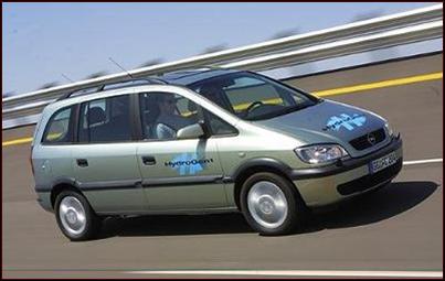
GM’s Opel Zafira fuel cell vehicle “making the loop” at the company’sDesert Proving Ground, outside Phoenix, Arizona. The Opel set a number of fuel cell performance records and offers a comfortable and impressive ride.
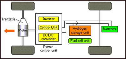
Schematic layout for a fuel cell powered vehicle using stored hydrogen.
Conversion of Vehicles to Use LPG
The Department of Mechanical Engineering sponsored student teams to compete in the “Propane Vehicle Challenge” for the 1995-96 and 1996-97 competitions:

(The 1996 Texas A&M University entry going through the road course competition.)
These competitions directed the students to convert a gasoline vehicle to operate as a dedicated liquefied petroleum gas (LPG) fueled spark-ignition engine and vehicle. For the 1996 Propane Vehicle Challenge the vehicle was a Chrysler minivan, and for the 1997 Propane Vehicle Challenge the vehicle was a Dodge pick-up. This student competition was intended to advance the development of propane-fueled vehicles, to encourage innovation in propane vehicle technology, and to provide student engineers with a hands-on learning experience.
The sub-system designs included LPG fuel storage and delivery systems, engine modifications (such as increased compression ratio by the use of domed pistons), a vapor fuel injection system, custom electronic controls, and specialized catalyst units. The vapor fuel injection system design included a vaporizer (for cold ambient temperatures) and port injection designed to inject LPG vapor at 276 kPa (40 psia).
The completed LPG-fueled engine possessed performance and efficiency parameters as good as, or better than, the original gasoline-fueled engine. In general, the exhaust emissions were lower for the LPG vehicle than for the original gasoline vehicle. For the 1996 Propane Vehicle Challenge, the Texas A&M University entry was awarded first place overall, and the award for the lowest emissions. For the 1997 Propane Vehicle Challenge, the TAMU entry achieved second place overall and the award for the Best Conversion.


(The 1996 Texas A&M University team at the competition site in Windsor, Canada.)
Copyright © 2001 – 2012 E3 (Engines, Emissions, Energy) Research Laboratory, Texas A&M University Department of Mechanical Engineering, College Station, TX 77843-3123, Phone (979) 845-4705, Fax (979) 845-3081